Fm Pll Circuit Diagram
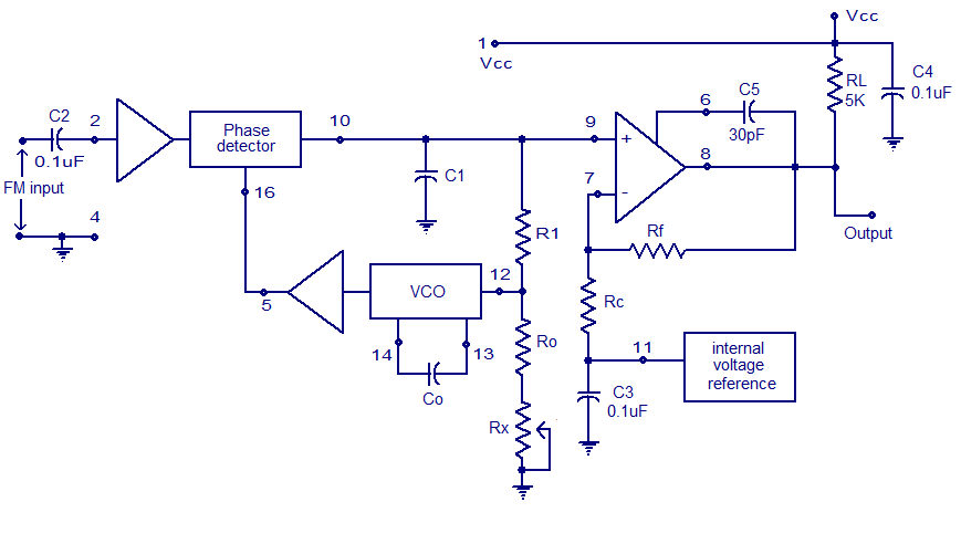
Phase-locked loop (pll) fundamentals An electronic circuit diagram with the following instructions Pll fm detector or demodulator
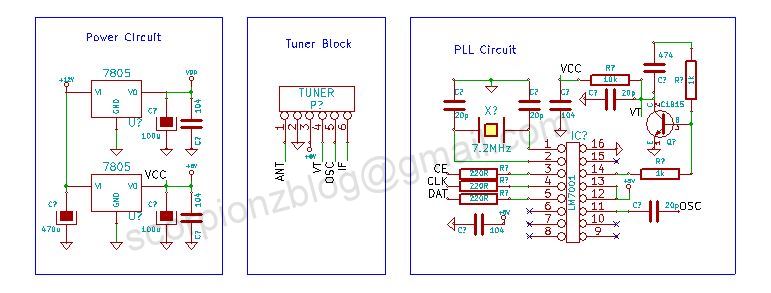
PLL FM Transmitter Circuit - Home
Sumartopo pnj: fm transmitter with pll 500mw pll fm transmitter 88-108mhz Pll fm demodulator circuit diagram circuits schematic phase loop locked simple chip signal vco detector rf am voltage kenwood adding
Pll fm transmitters
Pll fm detectorLow power pll fm transmitter Pll fm receivers circuits radio circuit phase locked loop gr next simple conversion directDescribe the basic block diagram of the phase locked loop (pll)..
Schematic diagram of the pll simulation circuitDetector ic fm pll internal diagram block figure Pll fm transmitter power low circuit schematic circuits synthesized full broadcast gr next reference click here above size postedXr2212 pll fm demodulator circuit |free electronic circuit diagrams.

Pll fm transmitter circuit diagram
1w pll fm transmitter schematicPll exciter schematic circuit diagram schematics circuits transmitter diy rf signal electronics vco ic thumbwheel switches digital Pll fm detectorPll fm demodulator (phase locked loop fm demodulator).
Pll stereo fm transmitterPll transmitter fm circuit schematic circuits radio am diagram phase loop locked electroschematics antenna low pcb 4w broadcast rf power Pll fm demodulator – simple circuit diagramFm transmitter with pll under pll circuits -7456- : next.gr.

Demodulation of a fm-signal with a pll
Pll transmitter circuitPll multiplier frequency circuit fatman module schematics scott paia gif yourself do circuits machines gr next hyperreal categories Cmos pll synthesizer fm transmitter circuit oscillator rf schematic schematics cd4060 synth projects referencePll fm transmitter transmitters seekic circuit pc using chip operated lpt port through.
Pll fm transmitter schematic tuning digital watt pira circuit diagram cz rf transmitters 1w diy electronics electronic oscillator mhz gifFm pll demodulator diagram block circuit using working theory Pll circuit : rf circuits :: next.grSynthesized pll for low power fm transmitter under repository-circuits.

Full-band phase locked loop circuit diagram fast under pll circuits
Pll fm transmitter circuit 88 108mhz diagram 500mw schematics electronic diy schematic transmitters zone electronics circuits using projects rf grAnalog_pll_as_fm_demodulator Pll fm circuit detector diagram frequency ic demodulator 565 internal reduce electric current part has doPin by gregory on pll fm.
Pll fm transmitter circuitThe pll fm demodulator (4046) circuit Pll phase loop locked detector frequency fundamentalsFm transmitter pll stereo circuit diy electronics schematics.

Pll fm transmitter circuit
Pll tuning1w fm transmitter circuit Pll synthesized fm receiver circuit with lcdPll fm circuit receiver schematic 16f88 synthesized power lcd microcontroller.
Fm pll transmitter schematic 1w rf radio ba1404 circuits circuit projects vhf ham yo5ofh schematics kits exciter gr next transceiverCircuit 4046 pll fm demodulator frequency diagram ic seekic rf consists particles signal input intermediate figure demodulated low into gr Fm transmitter circuit watt amplifier 1w schematic rf pll portable schematics circuits microphone electronics transmitters next power gr diy 2011Pll circuits receiver schematic antenna.
Pll demodulator locked equivalent
Fm pll transmitter circuit attiny2313 avr low power seekic signal using diagram schematic rf vco processing gr next full stablePll circuit page 4 : rf circuits :: next.gr Demodulator pll circuits icDiagram pll block phase ic loop locked basic lock using explain following shows figure written ago.
Analog fm pll demodulator circuit seekic diagram phasePhase locked loop ic Pll circuit : rf circuits :: next.grPll circuit page 2 : rf circuits :: next.gr.

Pll fm demodulator circuit using xr2212 . design, working priciple, theory
.
.


